Building a RichRap 3dr - Part 5 - Wiring it all up and completing the build
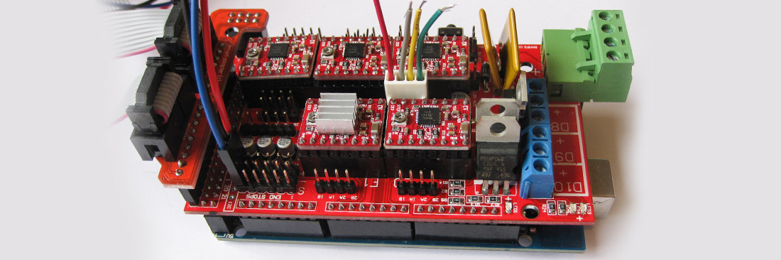
The brains of my 3DR kit is an Arduino system, which has a piggyback board called RAMPS which has the motor controllers.
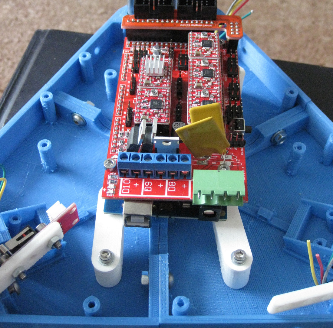
Each Servo on the RAMPS board has a ‘stepper stick’ which contains probably the components most likely to blow if something is configured wrong.
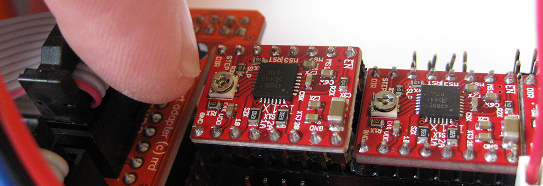
I quite like this idea of it all been modular and replaceable. You can see in the photo above the correct positioning of the stepper stick boards and I’m pointing to the adjusting pot which you use to ‘tune’ the steppers when configuring.
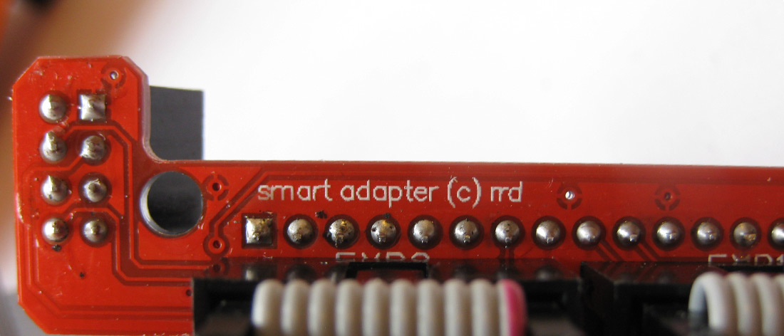
On top of that there is a further board which provides sockets to connect the LCD board to the main controller assemblies via ribbon cables.
The Arduino stack is mounted underneath the top of the printer and hangs down on some mounts. Here was one of the occasions where I got confused as the gcolbourne kit differed from the RichRap design for the board mounting. My kit had three white parts which sat on top of the screw pillars, pushing down scarily to hold them In place. If I didn’t get this right I was expecting that I was going to break one of these mounts trying to get it off.
In the end after quite a bit of head scratching I came up with this position to mount the arduino stack:
However - I forgot that I also needed to mount and adjust the mechanical endstop switches - so although these position got me in to the right ball park - if you are reading this for help building one yourself just remember that you may need to jigger these about a bit more.
Once the stack was mounted I was back in my comfort zone. Routing wires and resoldering the stepper motor plugs which i had cut off to thread the wires through the pillars. To make this neat I bought a set of different heat shrink sleeves from eBay so that I could make the wiring really neat.
One thing I was slightly concerned about was which stepper to wire to which controller, as well was the orientation of the plugs (these plugs were keyed, but the pinouts on the RAMPS boards were not. After reading a bit more it seems that you can plug stepper motors in the wrong way, just like normal motors, and their direction just reverses. Still not sure if this is the actual truth - but my experiments seem to confirm this. Of course the other thing was which stepper was X, Y and Z. On a traditional printer this is easy to work out - especially as the Z axis has two steppers, but on a delta all steppers need to move to make the z axis move, so which was which?
To be honest - I still don’t know.. But when it was all connected up it worked - so I must have guessed correctly.
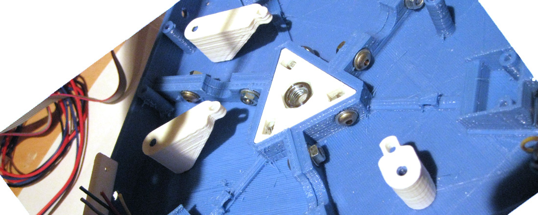
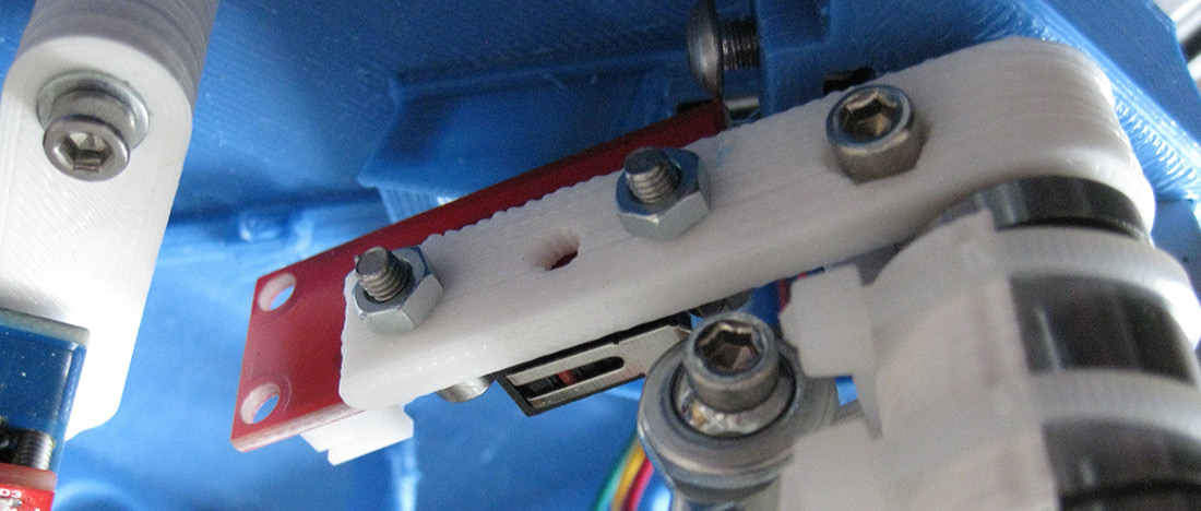
The final part of the control wiring was to mount and wire in the mechanical end stops - these were mounted on some white printed brackets you can see below. I found it easier to fit these with the bracket attached to the smooth rod but pointed away from the printer. But then once I all the hardware attached swinging it into position as you can see and then tightening up the bolts. Note from the picture the exact position of the ball socket at the end of the diagonal rod as it pushes on the metal of the microswitch. This position is critical (as I later found out)
Mounting the LCD screen was obvious so I won’t explain it - although I did break one of the printed mounting brackets because I tightened up the bolts too tight. This was my first real mistake. A bit of superglue sorted that though.
I won’t document the building of the hot end as this was really well documented on E3D’s website. But both gcolbourne and RichRap left me a bit in the dark about building the extruder assembly. This looked obvious - and actually it was - but the parts didn’t fit together. It transpired, after looking at pictures of them all over the web - that the printed part I had still had some of its support material left on it - as this was a perfect square and took a good deal of tinkering to remove it - I thought it was part of the assembly. Not a complaint - just an unexpected
Here is the final assembly of the control boards:
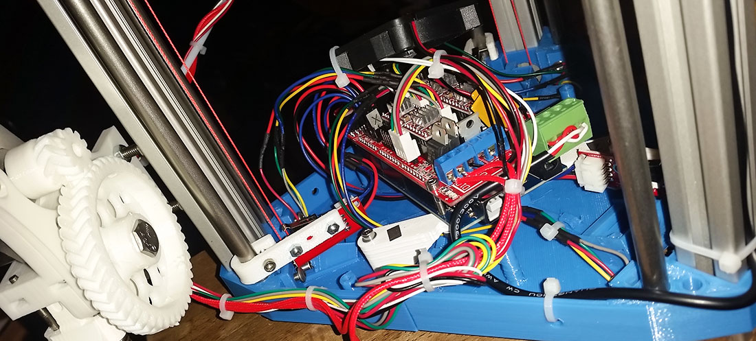
After this the power supply wiring was straight forward and I was ready to power up for my first print.. Or so I thought...
Next - Preparing to print
Back to Part 4 - tying on the carriages
8-May-2015 Add comment
blog comments powered by Disqus Permanent Link