A MonkMakesDuino and a Mac
Great specially designed prototype board
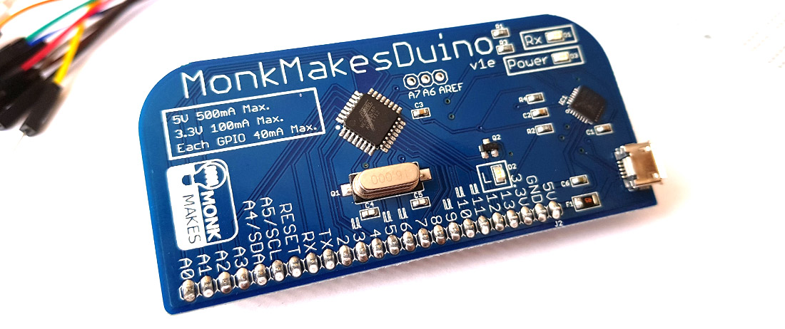
Yet another Kickstarter project arrived this week, MonkMakesDuino. This board caught my eye as it has been made to connect to a breadboard, and has a well supported serial chip so should work without incident on a Mac.
The board itself seems well made and looks very simple. I had ordered some extras with the reward so there was quite a lot in the box when it arrived:
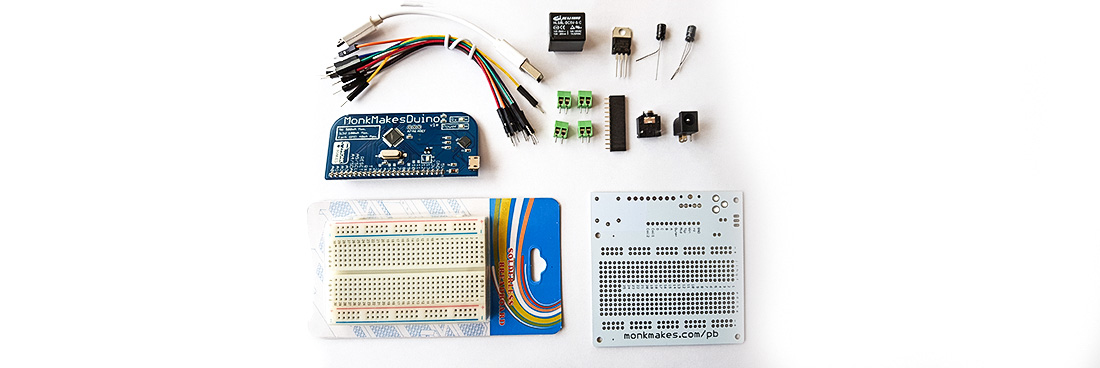
As this is designed to be connected to a breadboard I had included one of these and a pack of some other components which included a prototype board that interested me. I wont go into great detail about the extra parts here, but just deal with the ease of use of the Arduino side.
The comms chip onboard is a Silicon Labs one:
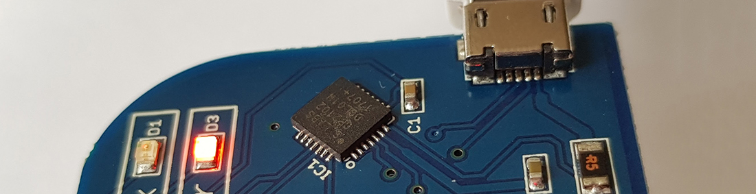
If you go to the Silicon Labs site there are drivers for several platforms, including the Mac. When I had received notification that the board had been shipped I went off and downloaded the drivers and installed them on my Macbook. There wasn’t much issue with these, download a zip file, mount the disk image and run the package installer.

After standard asking which drive I wanted it on, the drivers installed without further incident. Well I hoped they had. Without the board there was nothing really to test them on.
Once the board arrived and was plugged into the Mac, the LED started blinking – which seems to be a standard install test sketch for any Arduino based dev board currently. Nothing else happened on the Mac, again to be expected, so I booted the Arduino IDE and looked at the ports. Here was my new board showing up as a device I had not seen before:
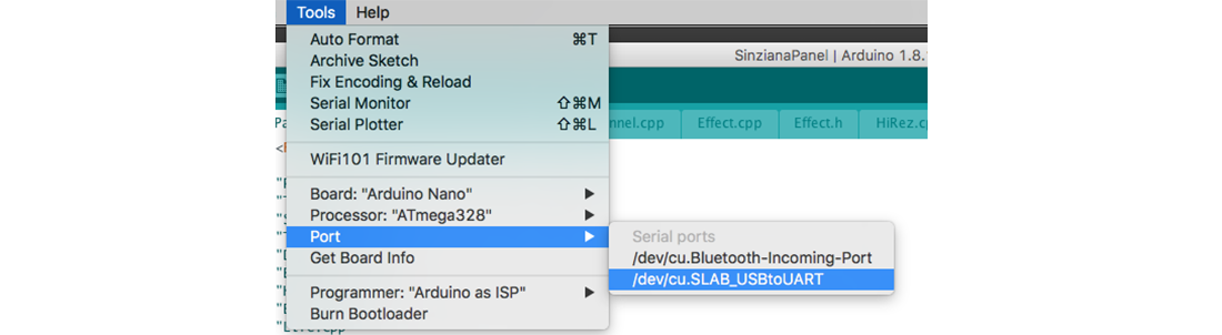
A quick check on the docs revealed that this chip is an Uno, so I had to change the board to match this on the IDE, and then I uploaded a local copy of fade – which is the PWM equivalent of blink. This uploaded to the board correctly, and stopped the LED blinking. There was no problem with this as the onboard LED wasn’t on a PWM pin, but I knew that there were not going to be any problems with flashing this board. I put a local copy of blink back on the board – making sure to specify pin 13 in the source and all now works as intended.
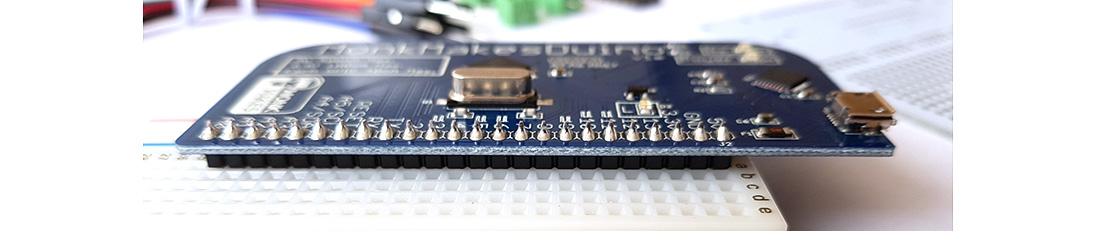
So now let's start using the board with a breadboard and its special GPIO headers. These are arranged in a single row. The headers on the bottom of the board fitted snuggly into the supplied breadboard. There are more rows on the board than on the gpio so I let the board hang over the side of the breadboard:
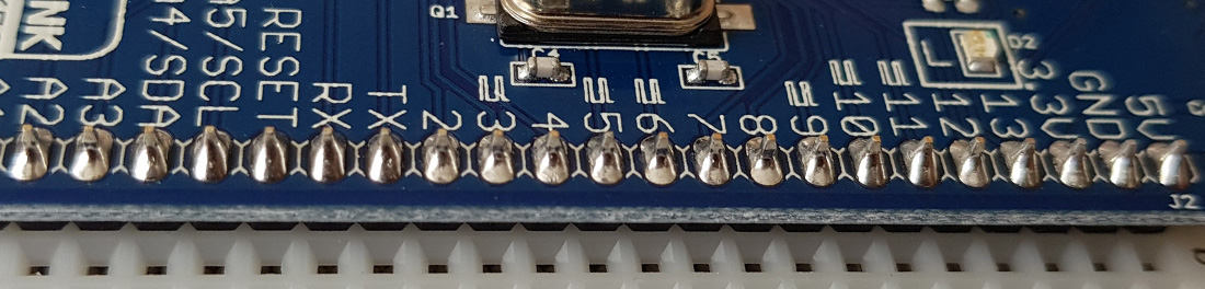
Looking closely at the board the GPIO is very clearly marked. For my test you can see that the PWM pins are clearly marked with a waveform icon above pins 3,5,7,10 & 11:
So to test the fade sketch, I ran some wires from the power and ground of the board to the power rails on the breadboard. These are the red and black wires in the photo below:
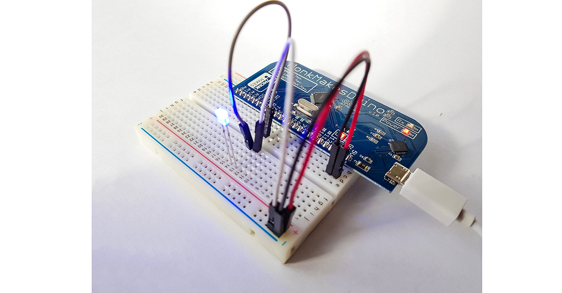
I connected pin 3 to a LED (brownish wire) and that in turn to ground (white wire) After I flashed the fade sketch back onto the card I now had a fading up and down LED. (I should have put a resistor in here somewhere to protect the current going to the LED. For this quick concept test I didn’t need to worry too much about damaging anything)
I really like this board - its a well made development of a simple idea. I think it will become my go to board for developing projects with before I port them across to cheaper platforms. You can watch a video of me wiring the board up below:
If you want one - hopefully there will be some for sale on the MonkMakesDuino website once the Kickstarter orders are all fulfilled.
14-Jul-2017 Add comment
blog comments powered by Disqus Permanent Link