Building a Raspberry PI system in a flight case
Part 1 - mounting a TFT screen in the lid
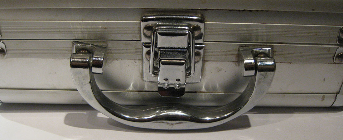
When I blogged about my Pi2 I hinted at my original Raspberry Pi project - which revolves around a small aluminium ‘flight case’ which originally contained a card game.
It struck me that I could create a ‘ruggedised’ PI system in this - which was a bit like a Pi Laptop. I say ‘ruggedised’ loosely as the flightcase is a bit of a fake, with wooden insides and metal look plastic on the sides.
Once of the things I wanted to do was to put a decent HDMI monitor in it, and it happened that you can get 7inch ones quite cheaply from eBay.
I was going to purchase a complete monitor but found you could buy ones as separate cards without the surrounding plastic. This was good as I would have had to take it out of the case and throw that away anyway - and saved me a few pounds
To mount the monitor parts in the top of the case I used black plastic foam board called foamex which could also buy very cheaply on eBay (about one pound per a4 sheet - if you buy 5) which is very sturdy and light - but you can cut accurately with a scalpel. It layers up well when stuck together with superglue. The foamex comes with a green protective film layer which I've not peeled off on most of these images. And you can drill it - and a correct size hole will self thread with machine screws.
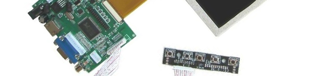
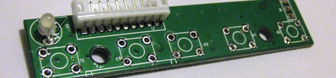
The monitor came with a logic board, the display and a control board with tactile buttons - as seen in the rubbish photo below:
By cutting holes in the foamex for the monitor and building up layers I was able to create a mount for the screen which I could unscrew to access the boards. Behind the scenes it looks like this:

You’ll see that I had to ‘modify’ the power and the HDMI leads here. I did this several times within this project by carefully cutting off the plastic moldings of the plugs so that I could change or alter the dimensions of the plugs. An example of this is the HDMI lead you can see above - which I modified so that it turned into a right angled plug. Once I had got the wires going in the right (angled) direction I built a foamex external shell for the plug and filled the inside with hot glue to protect the delicate wires
I originally drilled holes in the foamex board to mount the control board so you could operate the monitor controls - I was quite happy with those results:
But I couldn’t activate the buttons through the holes - even with a pen, and some of the buttons were even jammed in the activated mode making the monitor flash between video sources and not display the Pi.
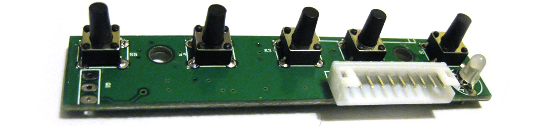
I found some tactile buttons on eBay which had a real long button:

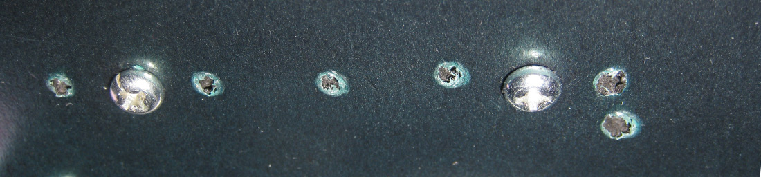
So was able to carefully desolder the existing buttons from the controls board
and mount some new ones like so
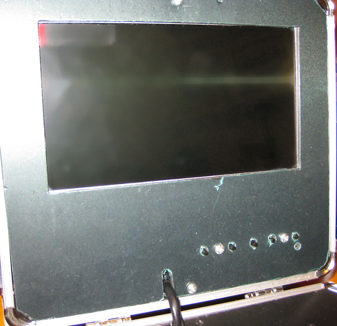
I would have preferred to have been able to laser cut the holes into the foamex for the buttons and the monitor screen - but I bought a 3D printer instead of a laser cutter. Here is the final look of the control buttons and the screen. Remember I'm still yet to peel off the protection film
I’ll walk through the rest of the project in a later post.