Making a Raspberry Pi mini arcade cabinet
When you are on a budget and have no space
A few months ago I saw Tested.com building a mini arcade cabinet called Porta Pi from Kickstarter. This was a beautiful laser cut cabinet with a nuke mini PC in it . Really that was what I wanted to do with my PI in a case project - but I could never get the controller to work and the screen didn't really work properly.
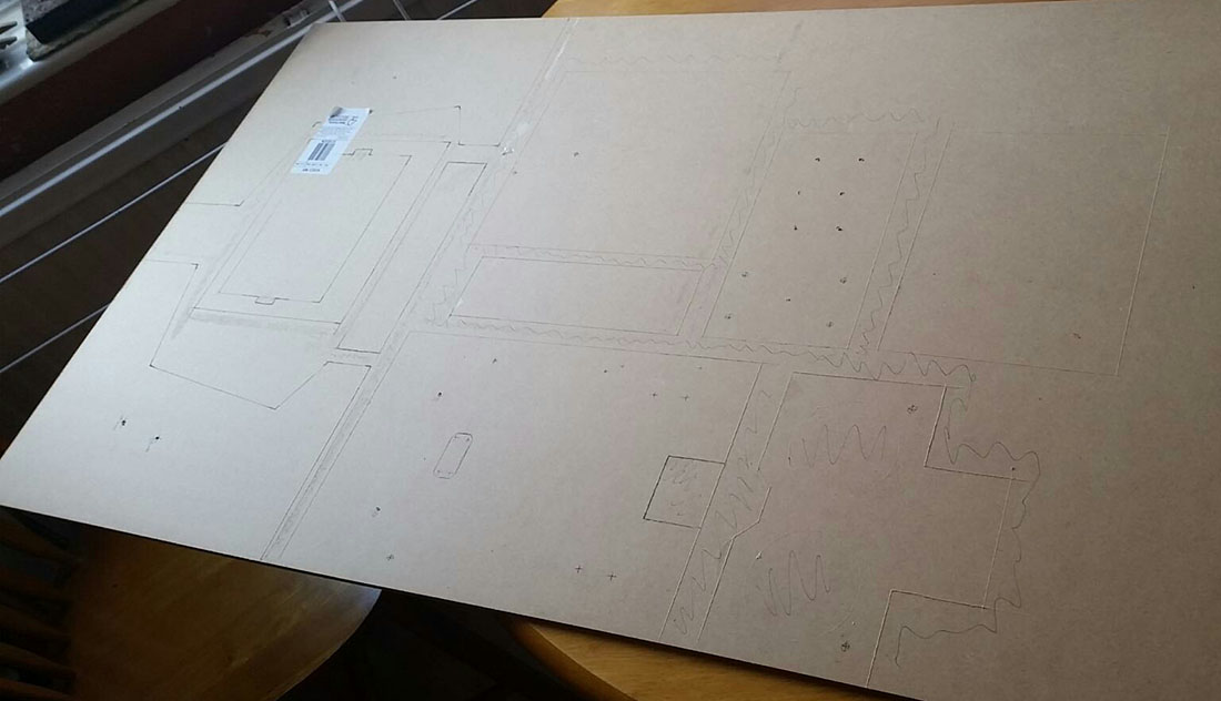
The kickstarter project and the nuke were more than I wanted to spend, but the designer, Ryan Bates has a website www.retrobuiltgames.com/ where I found he had posted some free plans for building a mini arcade. This was not the fancy machine tool path file to run through your CNC machine or laser cutter - this was just something you could print out and use as a template for a more manual process - which is what I did.
So after a trip to B&Q to buy some MDF and a short afternoon's work I'd got the pattern transferred to the board,
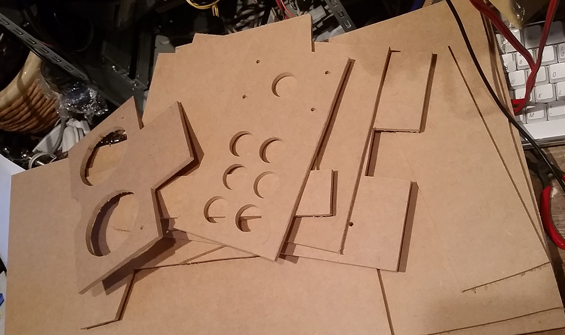
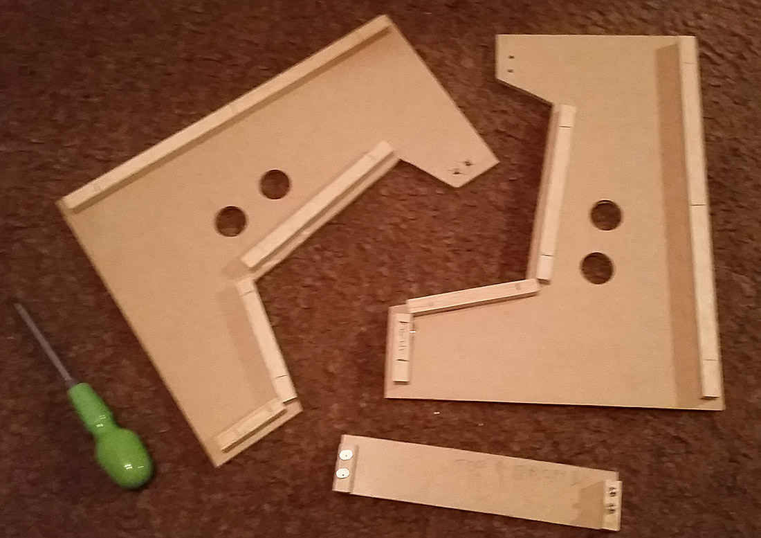
Next day I got the parts cut out using a drill and a jigsaw. For the button hole I used a 28mm hole cutter.
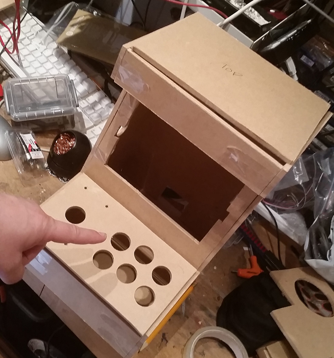
To check how all of the parts fitted I sellotaped it all together first.
Ryan Bates kits came with laser cut parts which have built in box joints unlike these plans. So once I had assembled it with sellotape I had to work out how to do the joints. I wanted to use what I had about, so I used some 12mm square wood that I had and drilled four holes in each joint which I could then put M4 countersunk nuts and bolts in to form the joint as below:
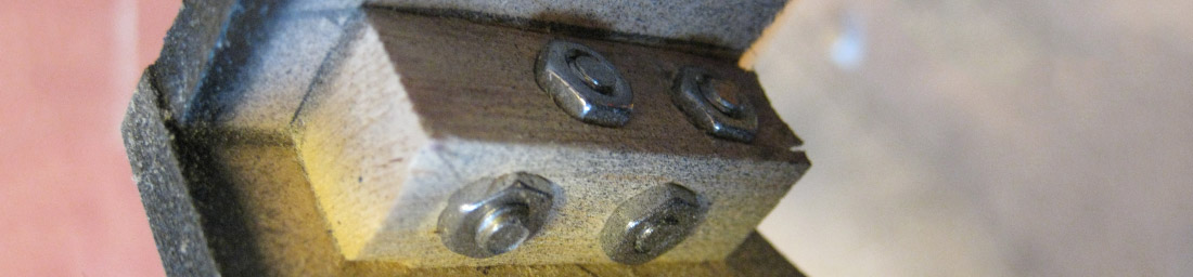
I also used superglue to stick the wood to one piece of MDF for each joint, so that I could keep that permanently there but take the joint apart if I needed. I used the other parts to get the joint blocks aligned:
That done it was relatively simple to connect all the pieces together.
Eventually I sprayed the pieces with car primer and then matt black from pound land, but after this used a more expensive plastikote clear coat over the top. I regretted my use of sellotape in the mockups here as it slightly damaged the mdf leaving a more porous surface that showed on the final paint job. For the screws that I wanted to be permanently fitted I sprayed over these - but used clean screws where i might want to take it apart.
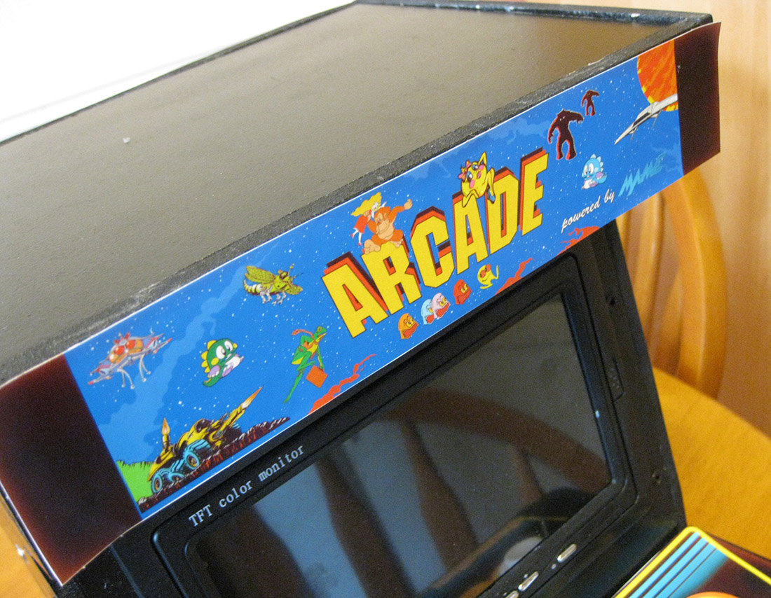
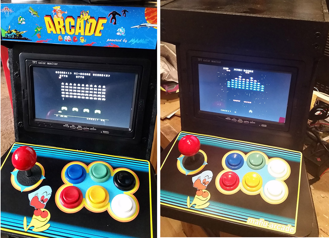
The plans were designed to use a TFT monitor which was made to put in the back of a car headrest.
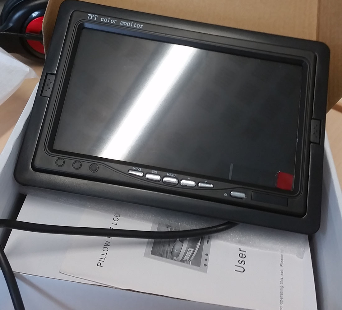
These cost around £20 from eBay, a 7" TFT Color LCD 2 Video Input Car Rear View Headrest Monitor DVD VCR Monitor UK somewhat cheaper than the HDMI enabled screen I had used in my pi in a case, but the most expensive bit of this project by far. Once this arrived it fit perfectly inside the cutout in the plans.
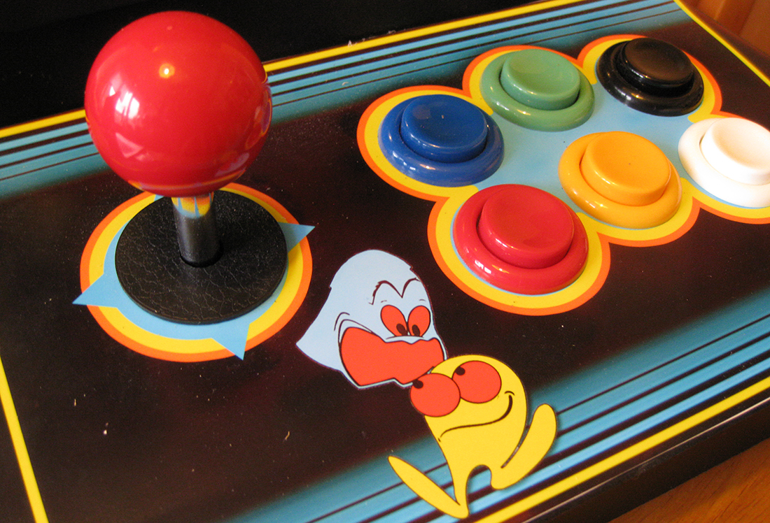
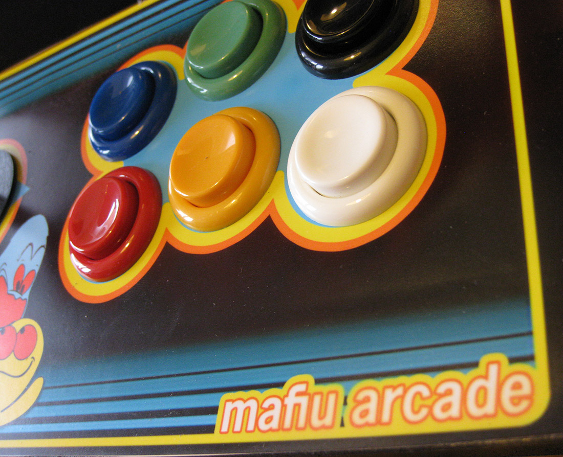
I'd tried to use a USB gamepad on my Pi in a case, but that seemed to crash quite often, so for this I wanted something better, so bought a board better designed for attaching arcade controls to. This was a Zero Delay USB Encoder PC to Joystick Arcade MAME JAMMA 2pin + Sanwa Push Button Therefore I also needed a set of arcade buttons at 99p each and a joystick. These all fit perfectly in the holes shown on the plan.
I noticed that Ryan sold as an option a larger control surface for his Portapi, so using the controls board from the plan by eye I worked out how to cut a larger panel which would fit on top of the sides as opposed to between them.
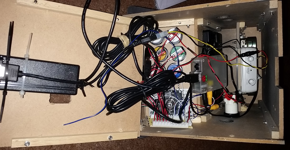
I used the same power brick as I did before in my Pi in a case, but this time left the hard drive connector on it, and then used a plug that I got from an old pc powersupply to wire out the power to both the Pi and screen.
For the sound I lucked out by finding a pair of Harman Kardon surround sound speakers for 50p at a car boot sale. Once I removed them from the plastic housing these fitted neatly in the speaker board. I was going to buy a separate amplifier board for these but in the end used a small pc speaker amp I had lying around. This took another feed from the 5v supply.
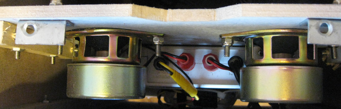
All of these parts were cable tied into the inside of the case, but there's so much room that I didn't really need to be neat. I left it so that the base would come off if I needed to access the components. Here is what it looks like from below:
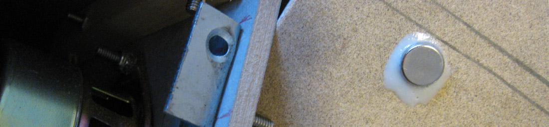
I didn't really want to put holes in the top of the case, but in the end put two iron brackets onto the speaker board, and then stuck two magnets on to the underside of the top board to attach it firmly but make it easily removable if I needed.
The final part was designing and printing some graphics for the minicade. I found some online and modified them to fit the plans and to look how I wanted them too. These were just printed out on coloured photo paper.
The best part of this project has been how whenever I showed it to someone they said ‘Wow', and then spend ages playing on it. It is a proud addition to my man cave and ideal as I don't have the room for a full size cabinet.

To improve this I would not have used sellotape to hold the parts together in the first place, and also would like to find a better way to insert the power cord into the back, maybe by getting a panel mounted euro socket and connecting that to the PSU inside. I would do the same thing with a network port in case I needed to update the Pi
I also discovered that you can spray car lacquer over a inkjet printout to see it - I will have to do this soon as the controls board graphics are beginning to fade.
29-Dec-2015 Add comment
blog comments powered by Disqus Permanent Link