Electrons: Driving a text display screen from an Arduino
Using the HD44780 Character LCD Display Module

Now that I've got an Arduino controlling things, I want some way to let it communicate with me. You can get them to talk back to a computer via a serial port, but really I want these experiments to stand alone (after programming) so I need another way.
Enter the HD44780 text display: a whopping £1.26, delivered from eBay. This came without headers fitted, so I used some from the electronic component pack which I mentioned in an earlier post. However, I'll also need a variable resistor (volume control) to make it work, taken from the same kit.
To get these working, the first thing you need to do is connect 5v power to the display. I connect Pin 1 of the display to the ground, and Pin 2 to the +5v rails from the YuRobot (the blue and red wires below).
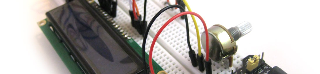
That sends power in, but you can’t see anything, so next you need to send power to the LED backlight. Pins 15 and 16 are the anode and cathode of the LED behind the display, so the red and black wires above are connected directly (I hope there's an onboard resistor) to the 3.3v rail and ground of the YuRobot. Now something lights up, but you can’t really see anything on the screen - you need to adjust the contrast of the display - and this is where the Potentiometer comes in. This sticks in the board quite well, as you can see below:

You need to send a variable voltage into the display to control the contrast, so you put 5v across the two outer pins of the pot (taken from the ground and 5v rail) and then connect another wire. I used a yellow one to Pin 3 of the display.
Now it gets exciting: turning the resistor reveals 32 white squares on the display - which shows that it's working and waiting for instructions.
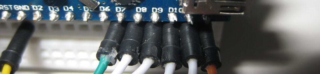
I wire power to my Nano board, then use Pins D7 through D12 and connect them to the display. Pins 9 to 12 of the Nano are the data pins, which connect to Pins D4-D7 of the display. Then D7 on the nano connects to Pin 4 of the display, and D8 to Pin 6. Finally you need to ground Pin 5 of the display. I think these pins send control signals through to the display, so that it can follow the timing of the data coming in on the data pins. Apparently the display has eight incoming data pins, but you only need to use four, so I have no idea what the extra ones are for.
So here's the wiring on the nano which goes to the display:

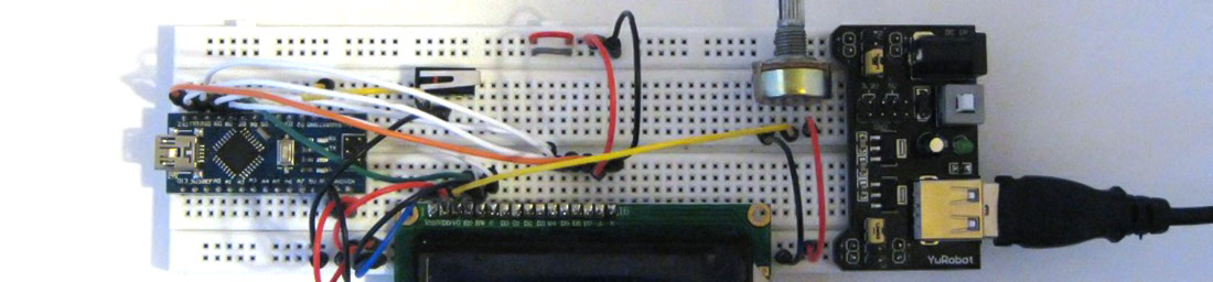
And here is the completed board. I add a small switch to reset the Nano board to this:
Finally, all I need to do is program the nano. Here's the code I use:
// include the library code: #include
#include// initialize the library with the numbers of the interface pins LiquidCrystal lcd(7, 8, 9, 10, 11, 12); void setup() { // set up the LCD's number of columns and rows: lcd.begin(16, 2); } void loop() { lcd.setCursor(0, 0); // Print a message to the LCD. lcd.print("Electrons!"); delay(1000); }
Looking at the code, we can see that this sets up the data pins which we'll be using - and also lets the library know we are using a 16x2 display. Another command sets the cursor to the top left of the screen, and then finally prints a message to the display.
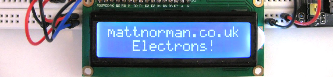
So after a bit of tinkering with the code, I was able to produce the following output:
In a later post I’ll extend this code, so that instead of just sending out a pre-programmed message, the Nano sends messages out based on some input that it gets.
18-Jan-2015 Add comment
blog comments powered by Disqus Permanent Link