Converting a laptop screen LTN141XF-L03 into an HDMI monitor - part 1 - connecting
Connecting and powering up the screen
I've used a couple of bare bones HDMI screens in Raspberry Pi projects but there is always the need to find a screen for testing the Pi, and plugging it into the main house TV is never popular. I read about a controller board from Banggood.com which allowed to to drive many different LCD panels and had many interfaces - including HDMI.
This post will explain what I did to get this board working with an LTN141XF-L03 panel salvaged from an old Samsung laptop.
Removing the LCD panel from the laptop wasn't too difficult, but if you are doing this I would recommend that you keep every wire and little circuit board that connects the screen to the main board of the laptop. You probably won't use these but I found them really useful as reference to the other bits that might be needed to get this to work.
I also left the metal bracket on the screen; useful for mounting it elsewhere later.
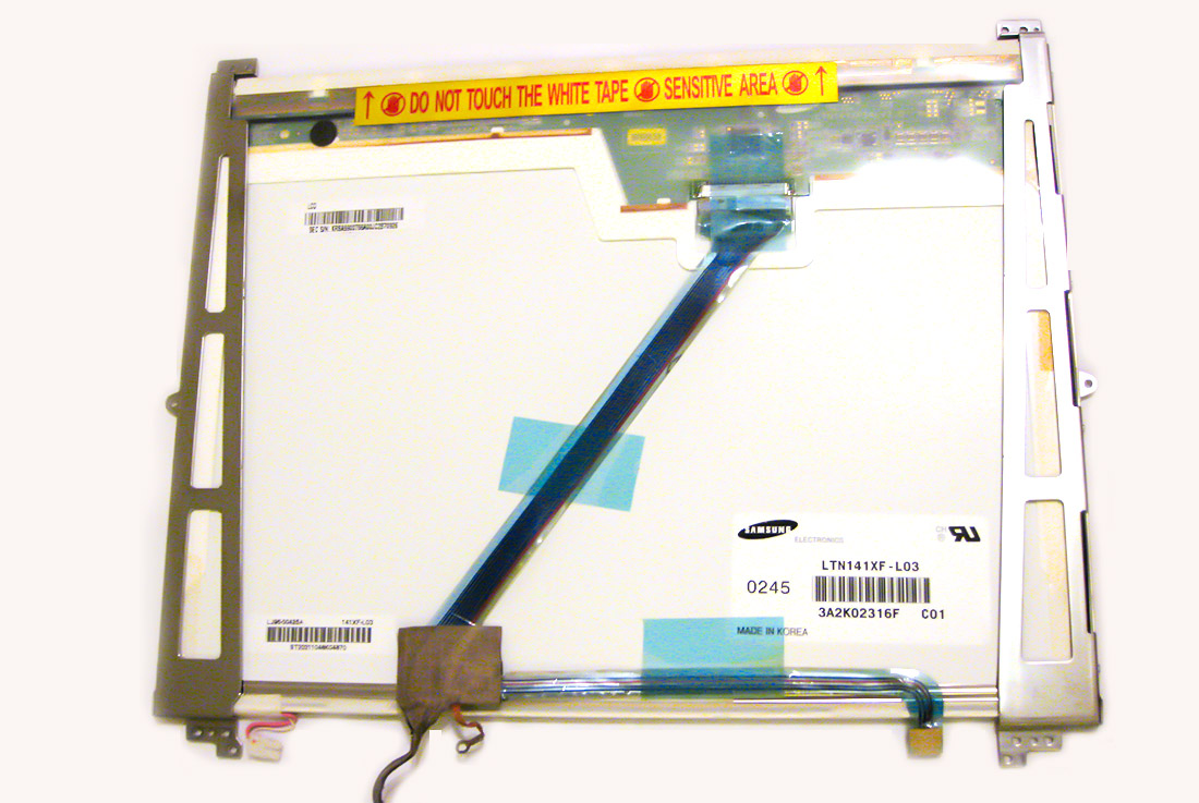
Once I had the screen out, the label revealed the exact model of the screen.
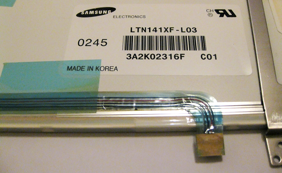
I looked this up on panelook.com which gave me some extra details about the screen such as its resolution (1024x768), interface (LVDS (1 ch, 6-bit)) and voltage (3.3v)
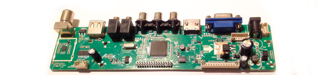
These were all supported by the V56 LCD Controller Board I had been looking at so I ordered that and waited.
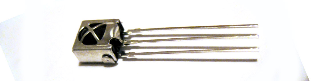
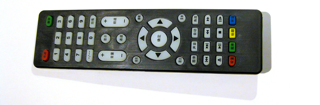
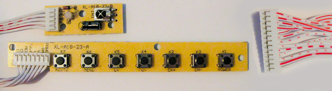
You can see the board as it arrived at the top of this post; a remote control (in Chinese!) and an IR receiver were also supplied.
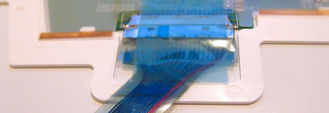
The original video cable which connected the laptop to the screen is a fragile ribbon cable, which had already broken at the laptop side. The cable connector was hidden under some blue tape, which, once peeled off, revealed the more standard connector underneath. This just pulled out.
Lcd4hobby had a blog post which used a similar board, and this outlined several different types of interface cable. A Banggood.com search for 'LVDS cable' found a couple so I ordered both. After a few days the following arrived:
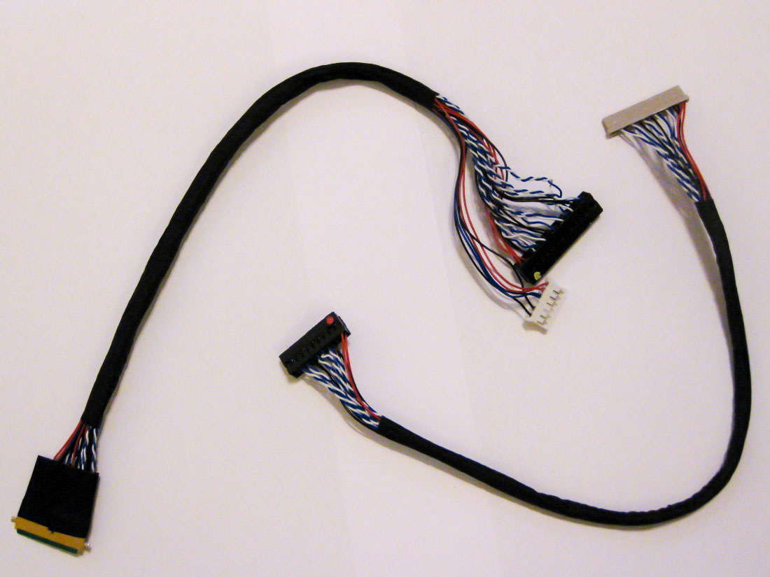
I was able to compare the original connector that I had removed from the screen to these new ones - and it turned out to be the one on the right in the picture - with one plug on each end (as opposed to the one with two plugs at one end).
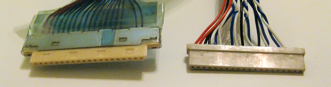
I later realised that this cable is the 20pin 8-BIt cable - which is what I could have worked out from the spec on the panelook site.
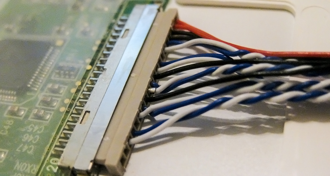
The new cable fitted beautifully in the screen.
The other end of this cable has a plug on it which is smaller than the socket on the V56 board, but pin1 was marked both on the board and the cable, so I plugged it in an powered it up. As I hadn’t powered the lamp in the screen yet, I tried to put a backlight behind the screen. Something was happening - but I couldn’t really see what was going on.
The lcd4hobby blog post mentioned about a control board, with several switches on it. Again off to Banggood.com and I ordered one of these. This also had a built in IR receiver and a multicolour LED, so I paused the project to wait for this to arrive - so that I could verify that the board was working.
Finally it arrived:
I popped this in the V56 board and powered up - the LED lit - went blue after a few seconds and then went back to red. I could see something happening on the screen - but not any detail. I could also now turn the board on and off using the remote control - however it seemed like it would reset itself after a few seconds.
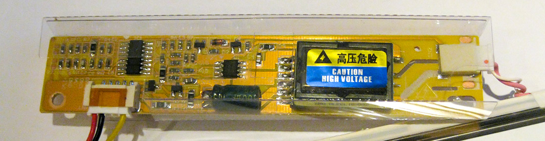
In the end I went back to eBay this time and purchased a universal inverter board to drive the light in the screen.
So once this was all set up and connected I held my breath and turned on the power. Again the same behaviour, the LED lit up red, then blue - then the screen flashed for a second and then the LED turned back red again. This had me scratching my head again for a few days until finally I saw a little light flashing on my bench power supply ever time the blue light went back to red - and realised that the PSU I was using was only 0.5 A and was limiting itself every time I tried to turn it on. I swapped to a beefier 6A PSU and my screen burst into life, well at least some of it - and it was in a far eastern language too. So much more config needed to be done.
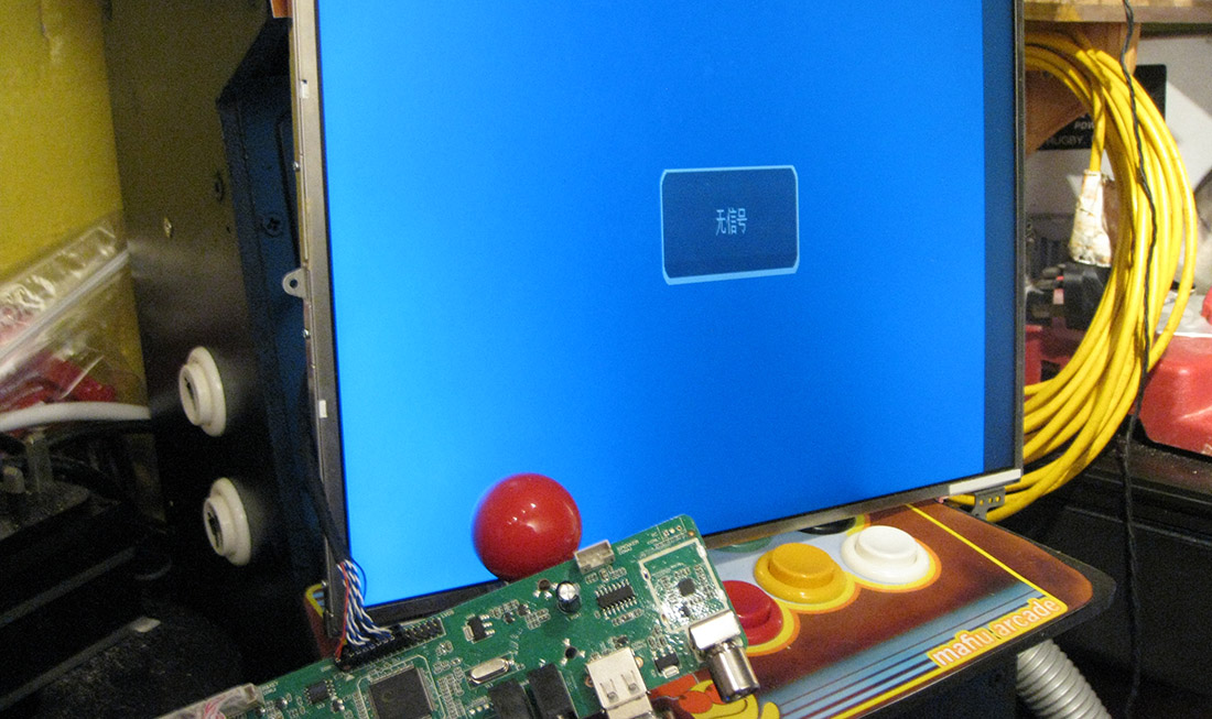
In my next post I will describe what I had to do to update the firmware of the board to get it to drive this panel correctly
Shopping list.
Here is what you need to buy or acquire to drive a ltn141xf-lL03 screen with the V56 board the way I did it:
- Working ltn141xf-lL03 lcd from a dead laptop
- V56 Universal LCD TV Controller Driver Board PC/VGA/HDMI/USB Interface (955022) (£10.35 from Banggood )
- 7 switch control board assembly Universal 7 Keys V29 V56 V59 TV Switch Keypad Board With Interface 955688 (£2.79 from Banggood)
- LVDS 20pin 8-bit cable 20Pin DF14 20-20 Signal 8 Bit LCD Screen Driver Board Line LVDS Screen Cable 977748(£1.13 from Banggood)
- Universal 1 lamp CCFL inverter board (1 Lamp CCFL Backlight Inverter Board kit For LCD Screen Panel Monitor PC laptop )(£4.90 from eBay)
- 4A PSU UNIVERSAL 12V 4A 60W POWER SUPPLY AC ADAPTER CHARGER FOR PC LCD LED TV MONITOR (£6.49 from eBay)
Total Cost: £25.66
(I could have got some of these parts cheaper had I have not bought them from UK eBay - but I wanted them quickly)
1-Jan-2017 Add comment
blog comments powered by Disqus Permanent Link