Electrons: YuRobot breadboard power supply
and more on breadboards
Part of the idea behind this project was to buy items for under a couple of pounds each time and use these to understand how the electrical components work. But one of the major ways to up the cost is to have to buy batteries to power the experiments. The trinket I have been using so far has been powered by the usb programming cable, but if I used one of these boards on a finished project I want a very cheap way to be able to simulate using batteries.
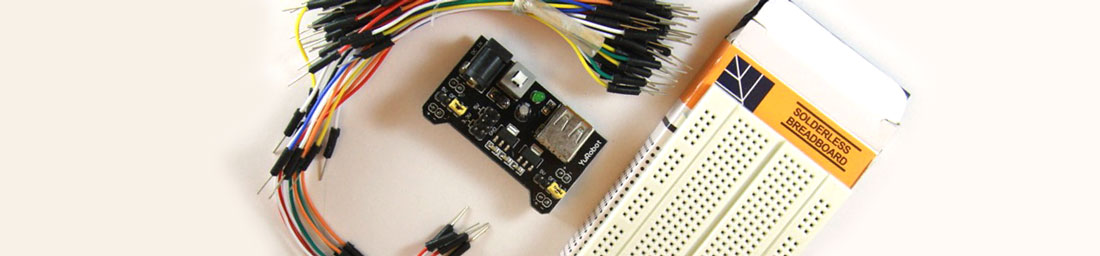
I explained about attaching a header to the trinket by inserting them in a breadboard, but when I was originally searching eBay for the breadboard I found the kit shown above for £2.38 (£3.73 once I added postage from China) This contained a breadboard, a power supply to add to it, and a lot of jumper wires which I could use on the breadboard and would save me having to make them.
When they arrived I discovered that these power supplies (called YuRobot) are made to use in Chinese schools to teach students about electronics. The excellent thing about them is that you can insert them into the breadboard like so:

When plugged in you use a standard USB lead, or a barrel plug power supply to power this board, and it automatically sends either 3.3volts or 5 volts into the breadboard to be used in your prototypes.
So maybe I need to now look in a bit more detail about how the breadboard works. There are many holes in this board, and the are connected together in a specific way. Here is what I worked out about the connections by using a battery and a bulb and testing each socket:
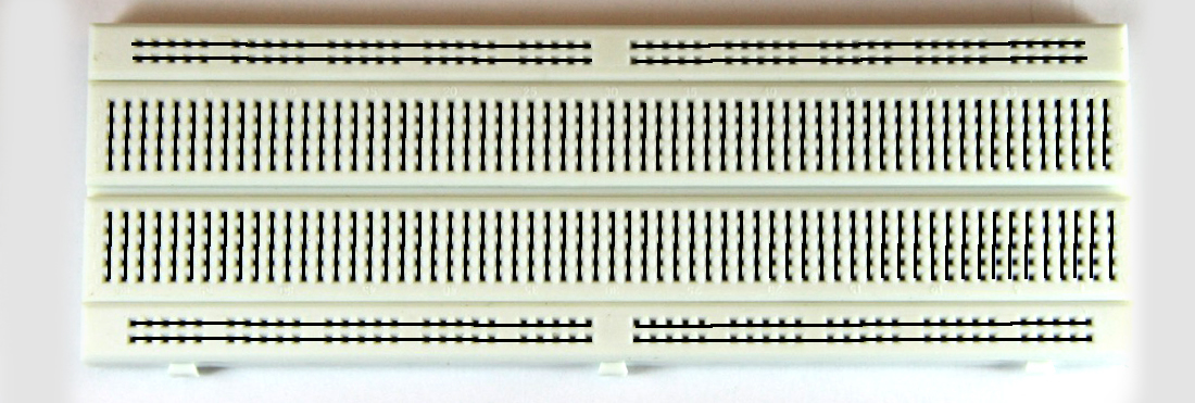
the black lines above show how each socket is connected or not to its partners. It appears to be convention that the horizontal lines are normally the power rails, that is the positive and negative connections for the attached circuit.
This means that when the breadboard PSU is attached and powered up the power is available as follows. You then dip in and out of these ‘rails’ as needed.
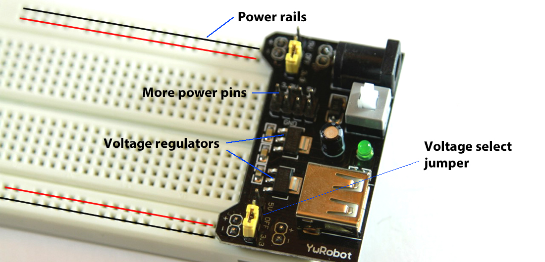
Now you can see the closeup of the board above you will note two yellow jumpers. By moving these you can change the voltage being sent on the powered rails - and even turn it off. Note also the power regulators. I’m sure at some point I will use some of these- but what they do is ensure that the power they are outputting is set to a specific voltage which doesn’t change over time. But once the input power falls below a certain value - these regulators stop powering the circuit. The are more relevant on battery powered circuits as the voltage from the batteries falls over time.
You’ll also see that the board also has a power light and a push power switch.
Here is an example of components on the board and you can see how they are connected into the power supply by their rail connections.
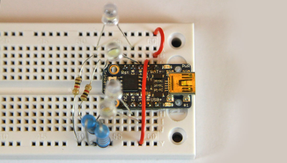
My next post will explain what I am doing with the components shown above
23-Nov-2014 Add comment
blog comments powered by Disqus Permanent Link