Analog Zero - first looks
Adding analog in ports to a Raspberry Pi
Analog Zero was a very fast kickstarter project which I got in on an earlybird reward because I was already backing another project by Alex Eames. The project got to funding in 85 minutes - which was pretty quick and only cost me £8. This project was a kit for a relatively simple shell for the pi zero which added 8 analog in ports.
I've read analog signals into an arduino but not into a pi yet, so this was where this experiment hopefully will lead.

The analog zero comes in a zip log bag as a bare kit. Its designed around a MCP3008 analog to digital converter which the kit has a socket for too. The early-bird version that I got had a few extra components as stretch goals.
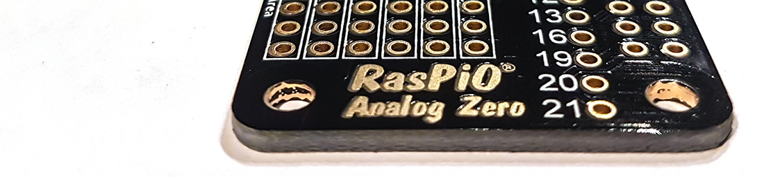
The board is well made, and as well as the chip and the socket you also get the GPIO header and a header for the analogue in, a jumper for the voltage reference and a couple of capacitors.
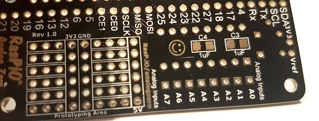
On the underside of the board there are pads for a couple of surface mount 1uF capacitors - which you can use if you have some and don't want to use the supplied bead ones - I think... You can see that above the board neatly brings out all of the GPIO headers and names the pins - which I like. There are also some areas for prototyping, for stuffing other components, and a couple of power and ground rails. I'll put the extra headers I received in some of these rows.
Building was relatively straight forward, and took about 15 mins. There were no instructions supplied but these were on the website. I tried going it alone but because there were a lot of holes on the board but not a huge amount of components to fill them with it was slightly confusing as what to go where - but only marginally. The biggest problem really was working which side to put the main components on and then the GPIO socket. The board took its solder well and I didn't have any problems with bridging connections with solder. You can see me building quickly it below:
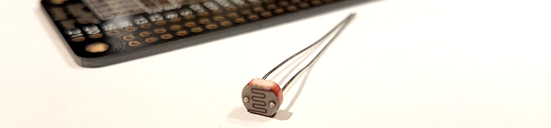
Because my kit was an early bird the full instructions on how to use this with the PI are not available at the time I write this. There is a brief guide but this assumes that I have more knowledge about programming the pi than I do. What I wanted to do, just for this post was to connect the supplied LDR (light dependant resistor) to one of the pins, run the supplied code, and then measure the light levels (by measuring the resistance from the LDR) and display that on the screen.
The sample code used a library called gpiozero, but the Pi I was running this on (ironically not a pi zero but a Pi2b) didn't seem to have that library available, so I couldn't get it to work, so I won't show anything here - I may explore this in a follow up post.
My current thoughts are that I can just use the general Pi GPIO library to talk to this board when its not connected to a zero. I'd like to try that but also no doubt more will be revealed when the full documentation is complete. I'm aware that I've not posted for a while though, largely due to me having a large amount of unfinished projects, so for now I'm going to get this posted and discuss how I got it working in a later post.
24-Jun-2016 Add comment
blog comments powered by Disqus Permanent Link