Extending my RichRap 3DR
Heated beds, diagonal arms and power supplies
I built my 3DR earlier in the year, and after using it for a while decided that I wanted to different filaments other than PLA. I’d ordered several test filaments and a lot of these needed a heated bed to allow the first layer to stick. So I decided that it would be an idea to add a bed to my printer which led to a series of upgrades that I hadn’t expected. I'll document some of these steps in this post.
I built my 3DR earlier in the year, and after using it for a while decided that I wanted to different filaments other than PLA. I’d ordered several test filaments and a lot of these needed a heated bed to allow the first layer to stick. So I decided that it would be an idea to add a bed to my printer which led to a series of upgrades that I hadn’t expected. This post documents some of these steps.
Buying a heated bed seemed like a simple affair, there are many available for around £15. But the main problem with getting one for a delta printer was that you needed a circular one. My print bed on the 3DR is 150mm diameter, and after a while I worked out that I could only get a 200mm heated bed, which meant that I would need to expand the base. I’d seen that RichRap had posted several pictures of people who had expanded the 3DR, which largely mostly meant printing out several expansion parts to fit between the three main pieces of the top and bottom of the printer. When I finally found some stl files which were small enough for me to print I managed to print a set out. It wasn’t the set I wanted but it would work. The hardest one to print was the top triangular boss and I had a few failed attempts:
The completed set:
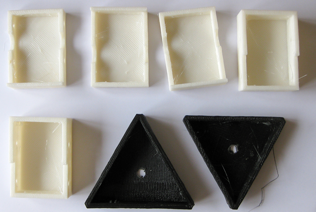
I needed to drill some more holes in the existing and new plates to make them all line up. I’ve since found stl’s for larger versions of the basic three parts which would lead to a more efficient build, but I probably would not be able to print these out at the right tolerances for use on a printer, and definitely not with my smaller printer.
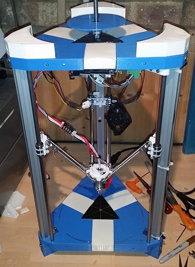
So after a couple of months I managed to get all the parts in and my 3DR extended.
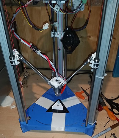
You can see the infill parts in white above, and the final black triangular top boss. The pictures above also compare the original boss part with the newly printed and installed one.
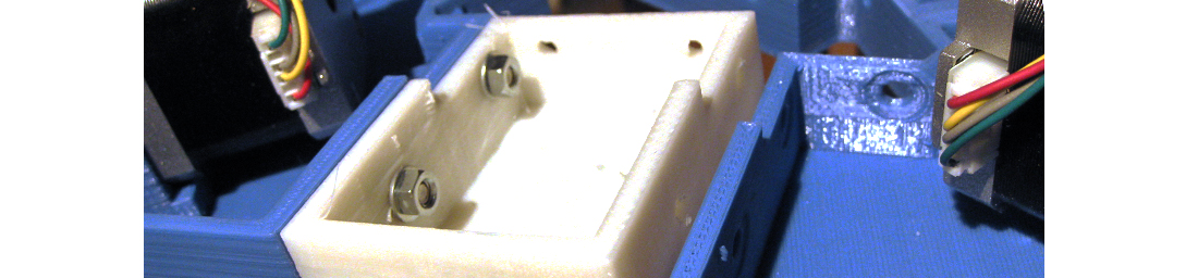
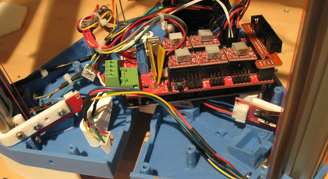
The physical printer frame wasn’t too bad to extend - some of the new screw holes where a bit fiddly to get in, and also I had to find a new way of mounting the ramps board as I had now altered the mount holes by adding the infill parts.
Thankfully due to the flexibility of the gcolbourn board mounts I was able to twist them around until I found a position which would fit the board.
A happy by product of taking the frame apart was I realised what was causing a problem I had with one of the carriages not sliding up and down smoothly. You can just about see what the issue was in the image below:
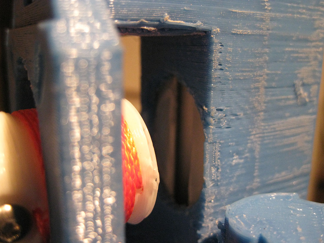
It seems that the pulley was rubbing on the inside of the frame corner - the friction was preventing smooth movement. It may have been tolerances in the material, or the print which caused this as there was no issue on the other two corners. In the end I put four washers between the stepper and the blue corner, which pushed the motor and the pulley slightly away from the frame. When it was all resembled the carriage is now as smooth as the others, and the prints are neater.
The next part of the quest involved acquiring a larger circular mirror - three actually - so I have two spare.
I decided I would get some nice heat proof wire to take from the power on the ramps board down the inside of the pillars and out to the bottom of the print plate
I cut a round piece of MDF to go under the plate on the off chance that the heated bed would melt the abs base of the printer. I also drilled a small hole in the centre of the MDF to poke up the thermistor, and cut out a small channel as well to bring the thermistor Here’s how I mounted it all, seen from the side:
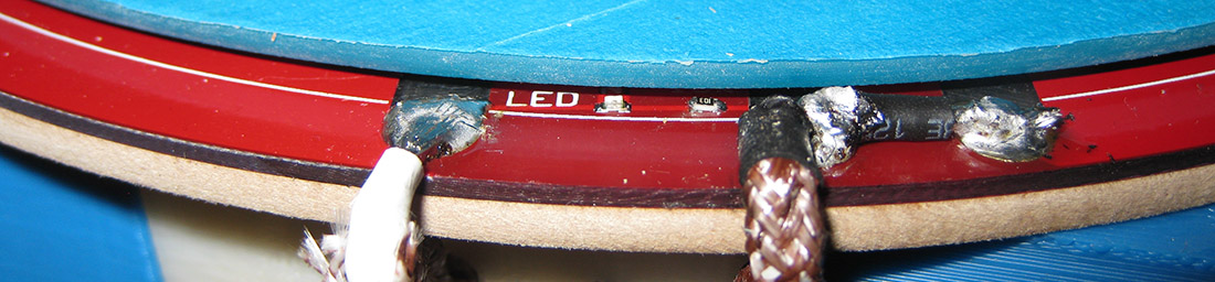
This was the first time I’d used this wire and its was a pity i didn’t put heat shrink on the first one as it would have stopped the sheath fraying. I could have done with a higher wattage soldering Iron too. I wired the other end of these wires back to the ramps board:
Now I was all wired up it was time to test a print. I needed to update the firmware to cater for a larger print area, so I changed the marlin config file and update the DELTA_SMOOTH_ROD_OFFSET parameter for the new size printer. Using Slicer, I loaded an STL file of a frog, and this time remembered to set the print bed temperature to about 30 - just to see if the bed started to warm up. When I selected the newly created gcode from the sd card on the printer as soon as I clicked on the file the printer reset itself.. I wasn’t expecting that.
I spent quite a while looking at the marlin config file to see what I had broken - but I hadn’t inadvertently edited anything wrong, but after a while realised that it must be that the small PSU that gcoburn had supplied with the kit may not have enough oomph to power the heated bed.
After a bit of investigation I discovered that you could power the heated bed from a PC power supply, so bought one of those for about £5 from eBay.
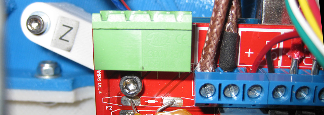
The next problem was this beast:
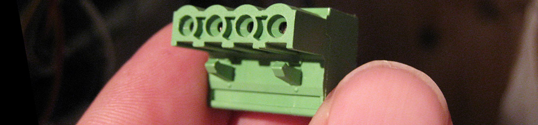
When I started the upgrade process I wanted it all to be reversible, so instead of unwiring my neat wiring I wanted to buy another of these plugs to connect the pc PSU to, so I could swap between them if needed. Again it took me quite a while to work out what these were called - but finally found you can get them from eBay with a search for "2EDG 4Pin Plug-in Screw Terminal Block Connector 5.08mm Pitch Right Angle."
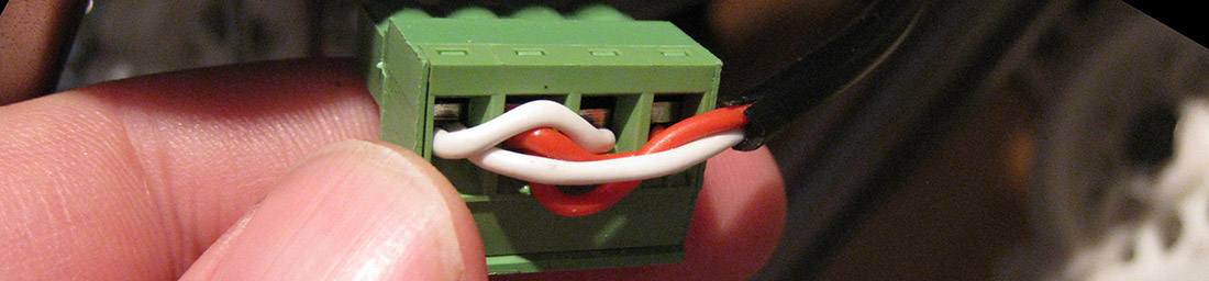
Now I could start to wire this all up, so I cut the connectors off the PSU and unravelled all of the wires to separate them into the different colours. I would need the yellow (12v) and black wires, along with the green wire to turn the PSU on and off. After cutting off the connectors I had a lot of spare wire which I ended up connecting all together so I could create a long umbilical to the printer so that I could make sure I could place the PSU on the bench next to it. Because I wasn’t sure of the power that the wires provided, or that the heated bed needed I doubled up the wires to make sure they wouldn’t overheat.
You can see below how I wired up the new green plug and how this looks connected to the printer:
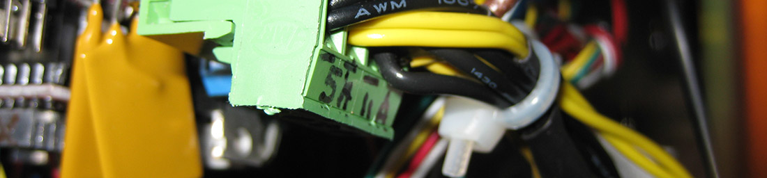
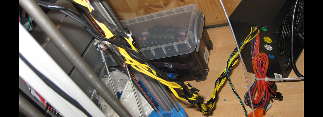
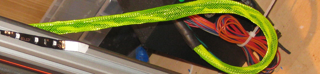
Although I tried to be neat with this it was quite messy, and after a while I ended up putting some plastic mesh over the umbilical to make it look neater.
Finally I put a small push to make/push to break switch between the green wire and a black wire to act as an on and off switch. You’ll note that I have bundled up the rest of the PSU wires I wasn’t using for potential future use (flashing lights, raspberry PI, USB sockets etc.
Now my PSU was more beefy, I loaded the code file that I created previously and hit print:

Now I was cooking, (or at least pleasantly warming some ABS, MDF and a glass tile..)
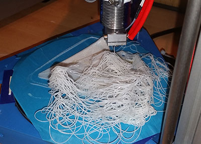
I could now print, both in PLA and ABS - and tried several new filaments which also required a heated bed. But as a by-product of the heated bed I now had a larger area to print on so next I needed to try a larger print. When I dialled in the next print I tried a larger one, and it failed abysmally. As the effector moved to the edge of the bed, the diagonal arms would now reach their maximum stretch, but as the carriage continued down begin to pull the effector back towards the centre. By messing about with the dimensions of the base I had inadvertently messed with he geometry of the printer, so needed to extend the diagonal rods.
The Gcolborn rods were M3 studding of about 120mm, and they had fancy metal rod ends. I managed to find a supplier of 200mm studding on eBay, and the more difficult to track down rod ends from a Chinese eBay seller.
I could have just got away with taking the rod ends off the originally supplied set but as ever I wanted to be able to go back to that so bough some more. I was glad I did as the quality of these were not too good, you only had to glance at one to strip its internal thread. After stripping two I realised that I could solve this by coating the thread with epoxy as I put it in, and measuring them all to the same length before it set.
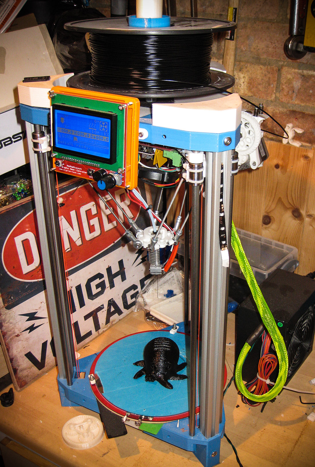
So here is everything now in place for my upgraded, larger print area, heated bed, enhance powered RepRap 3dr printer:
BOM for my 3DR upgrade:
- Filament for printing new extension pieces
- 200mm Heated Bed (make sure it comes with thermistor)
- 2m Wire for hot bed high temperature 1.5mm fibreglass wire (I probably should have just used twin and earth)
- 200mm Glass tile
- A4 sheet of 2mm MDF
- New green plug for ramps board (2EDG 4Pin Plug-in Screw Terminal Block Connector 5.08mm Pitch Right Angle).
- PC PSU
- Yellow mesh cable tidy
- PTM/PTB switch
- 6x M3 200mm studding (A2 Stainless Steel Threaded Bar / Studding.)
- 6x track rod ends (3mm Female Threaded Rod End Joint Bearing SI3P/K SI3T/K PHSA3 )
- Various new M3/M4 hardware to clamp new parts together and create the heated bed clamps
- Heat shrink for covering wires joined in making the umbilical, ending the wires and mesh
What I would have done differently with hindsight:
Wired the new green plug, using decent wire from the top of the printer to a pc power supply motherboard socket and barrel power connector attached to the side of the base plate.Then I could plug in the original power brick when printing objects not requiring the heated bed and use ANY pc power supply as the backup power for hotbed prints. As it stands when this PSU fails I have to mess about with a new one to get the printer working again - I would rather just plug a new one in using its already engineered sockets without all the re-wiring.
What I might do next
Create a nice box to mount the PSU in, hiding the spare wires and mounting the switch, I may also add a powered USB HUB to it to allow the use of LED lights to light the print bed whilst printing (for time-lapse of prints)
Thanks for reading to the bottom of this now vast post. I’ll leave you with a time-lapse of the new setup as a reward:
Leave a comment if you’ve done something similar below - or of this has helped you to extend your 3DR.
14-Dec-2015 Add comment
blog comments powered by Disqus Permanent Link