Messing with Meters - a Smiths RAF fuel gauge
brought back to life with an Arduino
It's time to play with some older technology now - what I would refer to as moving coil meters.
I've been reading about the Apollo programme over the last few weeks, thinking about how different the technology was then to what we have now. I was looking at the Apollo command module control panels and thought it would be interesting to try and produce a mockup of these using Arduinos and modern switches. This wasn't really going to work as any Apollo stuff is expensive, so I ended up buying a couple of aviation meters for a few pounds from eBay as I thought it might be interesting to connect these to some modern electronics.
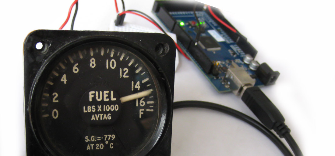
In this post I'll talk about a Smiths aviation fuel quantity gauge which I expected would work in the same way as a volt meter or a modern car fuel gauge.
The back of the gauge has two screw terminals one marked Positive (+).

On the other meter I bought it was marked 25V so if that's the working voltage of vintage aircraft I was safe using batteries across the meter to try and get some action. I started with an AA cell, which moved the meter to position 2. That's good because this meter was sold as seen, so I had no guarantee it would work. So now I needed to find the range of voltage I need to take the needle through its range, so moved to my bench power supply and found out that 1.4v moved the meter to the empty position and 3v to full. So now all I needed to do is work out how I could generate that voltage from the Arduino. I suspected I was going to need ohms law and a calculator, but In the end I was making this way too complicated. I wasn't even going to need math. An Arduino has 5v or 3.3v output and an analogue output function. So I should be able to drive the meter through its range without much if any external circuits with a trick using PWM (Pulse width modulation)
Because the Arduino is digital it doesn't really output an analogue voltage but turns the digital signal on and off very quickly which looks like the effects of a changing voltage. This is PWM (or my view of it - I'm probably absolutely wrong in my understanding of this - but what I think its doing matches what happens - so I'm going with this). There's an example sketch that comes with the Arduino called FADE, which changes the brightness of a led using the analogue output feature of the chip. Its pretty simple to use - in your sketch you just send a value to a pin, like this:
int ledPin = 9;
void setup() {
analogWrite(ledPin, value);
}
void loop() { }
The only thing I was really interested in was the part in bold - the rest you need to get the sketch to work. All I need to do then is connect the meter to this pin and the other wire from the meter to the voltage, and it should do something.
First of all I sent 0 to the pin. analogWrite(ledPin, 0); I thought that would be safe - but it shot the meter over to way passed full. I thought it might be because 0 may be null and the pin sends anything. if that was the case I set the value to 10: analogWrite(ledPin, 10); and the same thing happened.
So next I sent 254 (the range should be 0-254 I guessed) and nothing happened - the meter didn't twitch. Hmm… Lets try mid range - 125- now I got a result. The meter shot to around half way and violently swayed around a bit till it stabilised.
This trial and error was now getting a bit tedious - so I decided to write a better program - using some variable and delays so I could compile the sketch and test a couple of values at once.
So I wrote the following:
int ledPin = 9;
int nofuel = 174;
int full = 80;
void setup() {
}
void loop() {
  analogWrite(ledPin, full);
  delay(1000);
  analogWrite(ledPin, nodule);
  delay(1000);
}
This should just move the needle between the empty and full values, and I could change the values of nofuel and full until I hit the right values, which are what I above. In the end I got a bit confused because the high value moved the needle lower than the low value, so using variables helped me.
So I could now get somewhere. I could send a value to an arduino pin to set the fuel gauge to a number I could specify in the code. But there was still the issue of the violent movement of the needle. In the end I created a procedure to move the needle between two values using a smooth step value. Here is the final sketch:
int ledPin = 9;
int nofuel = 174;
int full = 80;
int meterOff=170;
int gaugeUnit=(nofuel-full)/16;
int currentVal=nofuel;
int randy=nofuel;
void setup() {
  analogWrite(ledPin, meterOff);
  fuelGauge(meterOff,nofuel);
  delay(1000);

  fuelGauge(nofuel,full);
  delay(2000);
  fuelGauge(full,nofuel);
    // wait for 30 milliseconds to see the dimming effect
  delay(2000);

}

void loop() {
  //loop
  randy = random(0,16);
  fuelGauge(currentVal,nofuel-(randy*gaugeUnit) );
  currentVal=nofuel-(randy*gaugeUnit);
  delay(4000);
}

void fuelGauge(int fromVal,int toVal)
{
  if (fromVal > toVal) {

  for (int fadeValue = fromVal ; fadeValue >= toVal ; fadeValue -= 1) {
   analogWrite(ledPin, fadeValue);
   delay(40);
  }
  }
    if (fromVal < toVal) {

  for (int fadeValue = fromVal ; fadeValue <= toVal ; fadeValue += 1) {
   analogWrite(ledPin, fadeValue);
   delay(40);
  }
  }
  if (fromVal = toVal) {
   analogWrite(ledPin, fromVal);

  }
}
This now does several things:
- The fuelGauge procedure (which is what I would call in other programs) takes two values and moves the needle between them, in steps of 1) If the value of both parameters is the same, it just leaves the value where it is.
- During the setup phase the procedure is called to take the meter from no-reading to empty, then over to full and back to empty again - this is a ‘self-test' to make sure the values are ok.
- Then the loop picks a random value for the needle to go to - moves it there using the procedure, and waits for a while.
- Lather, rinse, repeat.
Here it is in action with unnecessarily dramatic music:
The one problem I see with this is that the code needs to remember the current position of the meter. I'm not sure if I can have a global variable to store this - or if I can just talk to the pin and ask it what its value is currently. I'll work on that in fuelGauge2.0.
Also thinking about how I may use this - I may have a Arduino who's sole task is to drive the meter- and it listens to the two wire bus waiting for a value. Then I can drive the meter from elsewhere and maybe use it to display the room temperature or my internet traffic on my home broadband.
In a later post I'll talk about the other meter I bought: a Desynn Indicator Trim Gauge which I thought would be the same as the other really, but with two meters combined into one case. How wrong I was..
9-Mar-2016 Add comment
blog comments powered by Disqus Permanent Link